
The purpose of the Communication Test is to confirm whether communication with control units is possible via the VOCOM device and the OBD cable or connector. The communication test helps analyse the proper functioning of internal and external hardware interfaces, in particular the vehicle communication interfaces such as CAN 1, CAN 2, J1708, Ethernet, as well as the relays of the internal OBD Mux and Pull-up resistors.

- Start communication test - runs a one-time communication check.
- Start continuous communication test - runs the communication check repeatedly until you stop it.
- Detected circuit pins - shows which pins and data links are detected on the connected OBD cable or connector.
- Communication test results - displays the outcome of the test after it completes.
Communication Test Results
If the Communication Test is successful on the expected data links, it confirms that communication via VOCOM and the OBD connection is working.
If the Communication Test shows that communication is not possible on one or more of the expected data links, this indicates an issue with the OBD connection (for example, cable, connector, or pin contact). In this case, the diagnostic application may fail to identify the vehicle or equipment, or you may see mismatches and errors. If identification issues remain, continue troubleshooting in the diagnostic application.
Detected circuits
In the Communication Test, the OBD connector image shows the pins as they appear in the vehicle or equipment connector.
When the test is run, the detected pins will be colored.
| Voltage | Description |
|---|---|
| Battery voltage (Pin 16) | Battery voltage must always be present (12 V or 24 V). |
| Ignition voltage (Pin 1) | Ignition voltage must be present when J1708 is present, and its level shall be close to the battery voltage level. |
| Ethernet activation line voltage (Pin 8) | Ethernet activation line voltage must be present for vehicles that have Ethernet capability, and its level shall be around 75% of the battery voltage. |
Electrical architectures and data links
| Electrical architecture | J1708* | CAN1 | CAN2 | Ethernet** |
|---|---|---|---|---|
| VERSION2 | X | |||
| VERSION3 | X | X | ||
| VERSION3 (North America) | X | X | X | |
| VERSION4 T1 | X | |||
| VERSION4 T2 | X | X |
* J1708
- Pin 1 is expected to have voltage when the J1708 data link is present.
- The test can detect pin 1 voltage and J1708 traffic independently, but both are required to be present when using the diagnostic application.
** Ethernet
- The voltage level on the activation line is used to determine the Ethernet configuration.
- The difference between Ethernet types A and B is simply which pins are used:
- Ethernet type A (pins 3, 11, 12, and 13).
- Ethernet type B (pins 1, 9, 12, and 13).
Expected pins per electrical architecture
The communication test cannot say which pins are expected, but only which pins are detected.
VERSION2

VERSION3

VERSION3 (North America)
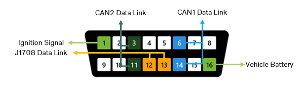
VERSION4 T1

VERSION4 T2

Communication Test for T2 vehicles
Note: For T2 vehicles, the Communication Test validates communication only to the first Ethernet node. It does not validate communication to TGW3 or SEM2. If there are issues communicating with TGW3 and/or SEM2, the root cause is likely related to internal Ethernet communication.

How to interpret the results
- If all expected pins are detected for the vehicle’s electrical architecture, this indicates that communication with control units on the different data links is possible.
- If communication is detected on the expected data links, but Tech Tool still cannot identify the vehicle, the issue is likely within Tech Tool. Try restarting the computer.
- If communication is not detected on an expected data link, the issue is likely the physical connection. Inspect the OBD cable pins and the terminals in the vehicle connector.